
Map title
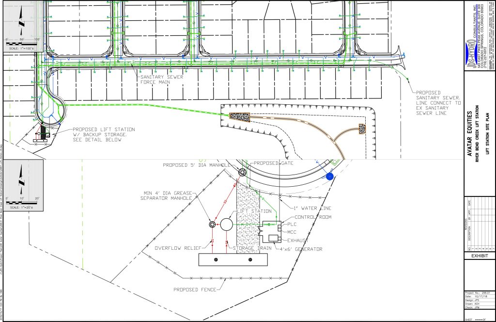
River Bend Creek Lift Station – Lift Station Site Plan
Text on map
Avatar Equities
River Bend Creek Lift Station
Lift Station Site Plan
JDS-Hydro Consultants, Inc.
545 East Pikes Peak Avenue, Suite 300
Colorado Springs, Colorado 80903
(719) 227-0072
Disclaimer: The contractor shall verify all dimensions. Any errors or omissions shall be reported to JDS-Hydro Consultants, Inc. JDS-Hydro assumes no liability for unauthorized changes and/or revisions to the plans.
Project No: 296.01
Date: 10/17/18
Design: JPS
Drawn: ACH
Check: JPM
Site plan labels:
- Proposed sanitary sewer, line connect to existing sanitary sewer line
- Sanitary sewer force main
- Proposed lift station with backup storage. See detail below
- Proposed 5 foot DIA manhole
- Proposed gate
- Proposed fence
- Minimum 4 foot DIA grease separator manhole
- Overflow relief
- Lift station
- Storage drain
- Control Room
- PLC
- MCC
- Exhaust
- 4 foot by 6 foot generator
- 1 inch water line
Alternative Text for Map Frame/Map Description
A schematic of the River Bend Creek Lift Station site plan and a detailed schematic of the list station
Text Version
A schematic of the River Bend Creek Lift Station site plan and a detailed schematic of the list station.
The larger schematic shows a larger area, a scale of 1 inch equals 1 foot, of the proposed lift station along with unlabeled roads and the proposed routing of new sanitary sewer, force main and water lines for the project.
The detailed schematic shows the lift station complex within a proposed fence and access to a proposed gate. There is a proposed five foot DIA manhole outside of the gate, and a line labeled SS runs to a minimum four foot DIA grease separator manhole inside the fence. From this smaller manhole, the same labeled SS lines run in two directions, one to the south labeled overflow relief, and one to the east to a circle labeled lift station. This lift station has a labeled SS line that is also labeled storage drain. From the lift station, a labeled S line runs east to a labeled control room, and this room contains labeled elements for PLC, MCC, exhaust and a 4 foot by 6 foot generator. A 1 inch water line is also running into this control room, and runs north outside the fenced area. From this control room, the S labeled line runs north and northwest and outside the bounds of the detailed schematic, connecting to the proposed lines in the larger schematic plan.